
WallSwitch - USER MANUAL
INSTRUCTIONS FOR USE WallSwitch The WallSwitch is a device that combines the functions of a wireless on/off power switch for electrical devices with a power rating of up to 3 kW, as well as a power consumption detector. The device's compact body conforms to European standards.

WallSwitch User Manual
The WallSwitch is a device that combines the functions of a wireless on/off power switch for electrical appliances with a power rating of up to 3 kW, as well as an energy consumption detector. The device's compact body is designed for installation in standard European socket boxes.
⚠️ Wall switches should only be installed by a qualified electrician! Regardless of the type of circuit in which the device is installed.
WallSwitches can only connect to Ajax-based security systems (they cannot be linked to third-party systems) using the Jeweler security protocol, with a range of up to 1,000 meters in an unobstructed environment.
WallSwitch only works with Hubs. Connections to ocBridge and uartBridge integrated modules are not provided.
The Ajax security system is capable of operating independently, but users can still link the system to the main monitoring centers of security companies.
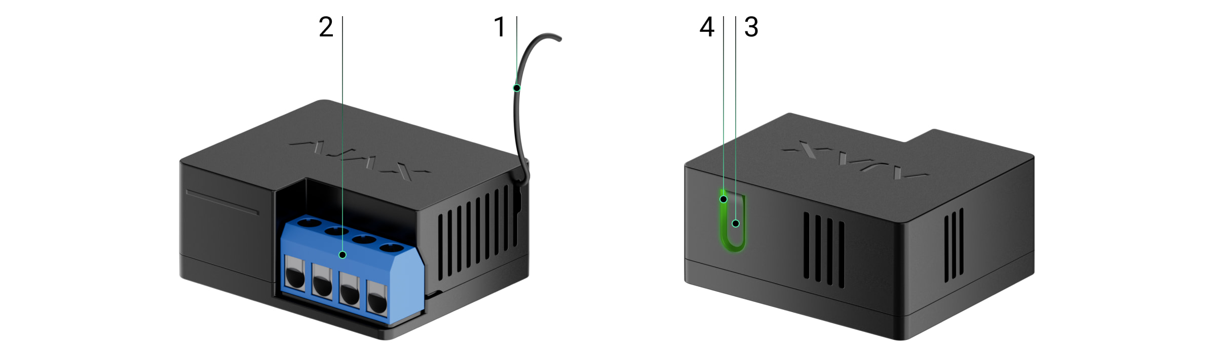
Features and details
-
Antenna
-
End-to-end link
-
Function button
-
Traffic lights

Terminal input port:
-
L terminal — hot wire input.
-
N terminal — neutral wire input.
Terminal output port:
-
N terminal — connects to the neutral terminal of the device.
-
L terminal — connects to the hot end of the device.
The operating principle of a Wall Switch
The WallSwitch's terminal input is connected to the main cable (with live and neutral wires), and the output is connected to the system's input socket or power source in the room. The WallSwitch switches the 220V power on/off according to scenarios or user commands via the Ajax Security System application.
The WallSwitch is equipped with protection against voltage fluctuations exceeding the 161V - 264V range or overcurrent exceeding 13A. In this case, the power supply will be interrupted and resume after the voltage and current normalize.
The maximum resistive load on the relay is 3 kW.
You can view the power consumption of electrical devices connected via the WallSwitch through a power meter on the app.
Connect the sensor to the Hub.
Before starting the connection:
-
Install the Ajax app on your phone and follow the instructions to set up the Hub (Hub, Hub Plus).
-
Create a user account, add the Hub to the app, and create at least one room.
-
Open the Ajax application.
-
Turn on the hub and check your internet connection.
-
Check and make sure that the Hub is in the Disabled mode and not updating (check the status displayed in the application).
⚠️ Only users with administrator privileges can add new devices to the Hub.
How to connect a device to the Hub:
-
Select “Add device” in the Ajax app.
-
Name the motion sensor device, scan the QR code or manually enter the device's code into the app (the code is located under the lid and on the box), and select the Room for the device.

-
Select “Add” - the countdown will begin.
-
Press the WallSwitch function button (or apply a load of not less than 20 W to the device, for example, by turning on an iron or electric kettle).
For the device to function effectively and without interference, the sensor must be placed within the wireless coverage area of the Hub (with a protective object).
A request to connect to the Hub will be sent shortly after the device is powered on. If you are unable to connect to the Hub, try turning the device off and on again after 30 seconds.
Once connected, the sensor device will appear in the list of connected devices. The frequency of signal scanning will depend on the settings on the Hub, with a default of 36 seconds.
When first switched on, the relay is in the open state! After removing the WallSwitch from the system, the Ajax switch will open the relay!
Device states
Devices → Wall Switch
|
Category |
Value |
|
Signal strength |
Signal strength of the connection between the hub and the device. |
|
Connect |
Connection status between the hub and the device |
|
Activate |
Relay connection status (on/off) |
|
Voltage |
The current voltage is passing through the relay. |
|
Electric current |
Current at the relay input |
|
Power consumption |
Current power consumption in watts (W). |
|
Power has been consumed |
The electrical energy consumed by the device is connected to the relay. The counter is reset when the relay loses power. |
|
Software |
The device's software version |
|
Device ID |
Device unique identification ID |
Device settings
Devices → Wall Switch → Settings (⚙️)
|
Function |
Content |
|
first line |
The device name can be customized. |
|
Room |
Select the room where you want to add the device. |
|
Current protection |
If activated, the power will be shut off if the current exceeds 11A; in the inactive state, the threshold is 16A (or 13A if continued for 6 seconds). |
|
Voltage protection |
If activated, the power supply will be shut off in the event of a voltage surge exceeding the range of 161 - 264 V, and in the inactive state - 0 - 500 V. |
|
Reactions upon Activation/Deactivation |
Select the response action for the relay upon activation/deactivation:
The device can respond independently to each Activate/Deactivate signal. |
|
Response in night mode |
If activated, the programmed activation/deactivation will also work in night mode. |
|
Check the wave intensity. |
Switch the device to signal strength testing mode. |
|
User manual |
Open the device's user manual. |
|
Unconnect the device. |
Disconnect the device from the hub and delete all settings. |
Signal
The WallSwitch indicator light may illuminate green depending on the device's status.
The green LED on the WallSwitch will blink continuously if it is not assigned to a Hub. When a function button is pressed, the green LED will light up.
Check the touch screen.
The Ajax security system allows for testing to assess the functionality of connected devices.
The testing modes will not start immediately but after a 36-second cycle when using the default settings. The start time of the test depends on the scanning cycle settings of the sensor device (see the “Jeweller” settings in the Hub settings).
-
Check signal strength
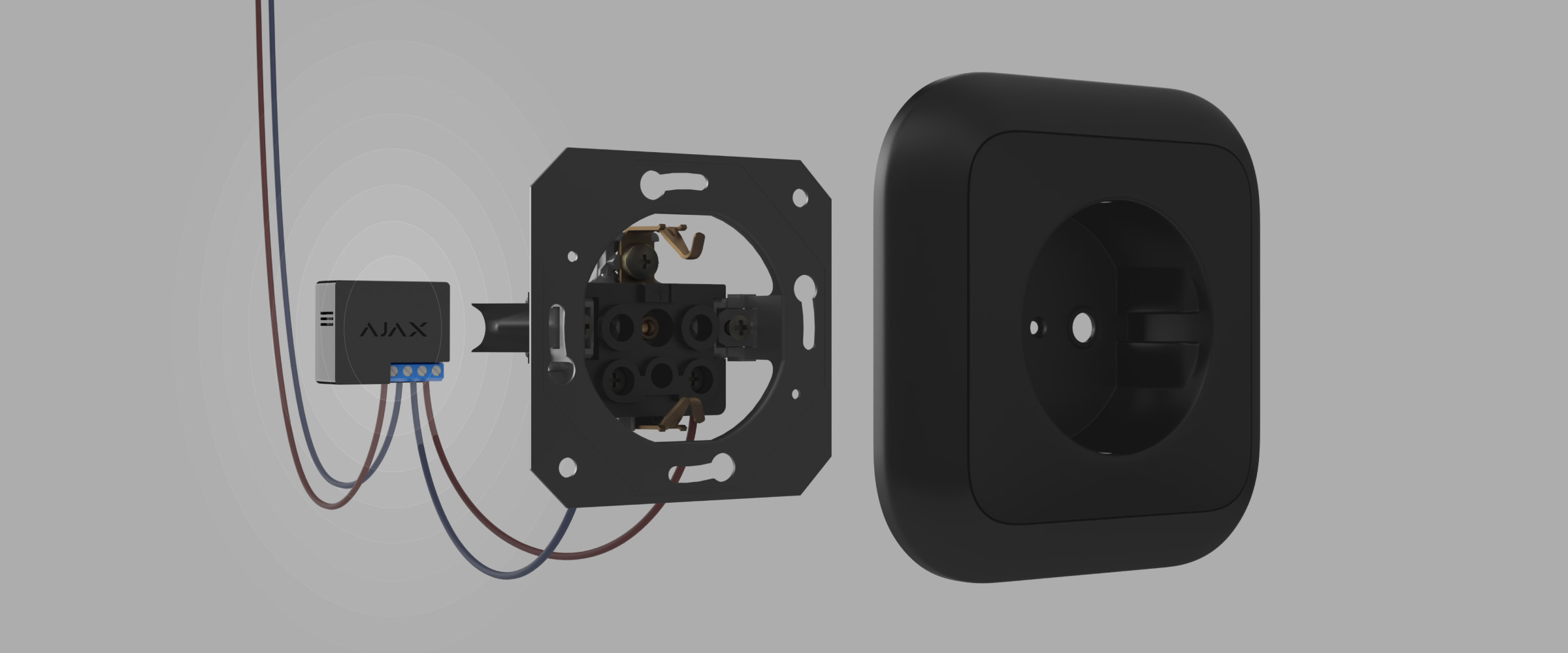
Equipment installation
Wall switches should only be installed by a qualified electrician! Regardless of the type of circuit in which the device is installed.
Wall switches are designed for installation inside socket boxes with a diameter of 50 mm or more and a depth of at least 70 mm. The relays can also be installed in extension cords and other circuits supplied by 220 V.
The communication range with the central hub in an environment without any obstructions between devices is up to 1,000 meters. Please take this into account when choosing the location for your Wall Switch.
If your device has a low or unstable signal strength, use a ReX radio range extender.
-
Disconnect the power to the cable that the Wallswitch is connected to.
-
Connect the room's electrical system cables to the WallSwitch terminals according to the following diagram.

-
Connect the socket to the Wall Switch using the included connecting cable or an electrical device with a cable of sufficient cross-sectional area. You should use cables with a cross-sectional area of 1.5 - 2 mm2.
Do not connect loads exceeding 3 kW to the Wall Switch. When connecting loads, strictly adhere to the connection diagram, as incorrect connections can cause equipment malfunction and/or property damage.
When installing a WallSwitch in a socket box, route the antenna outwards and place it under the plastic frame of the socket. The further the antenna is from metal structures, the lower the risk of signal filtering (and attenuation).
In any case, do not shorten the antenna! Its length is optimal for operation within the radio frequency range being used!
During the installation and operation of the WallSwitch, please adhere to general electrical safety rules for the use of electrical equipment, as well as the requirements of electrical safety regulations. Disassembly of the device is strictly prohibited. Do not use the device with a damaged power cord.
Do not install this device:
-
Outside
-
Inside a metal wire box or circuit board
-
In areas where the temperature or humidity exceeds the device's operating limits.
Maintenance
The device requires no maintenance.
Technical specifications table
|
Feature details |
Electromagnetic relay |
|
Relay lifespan |
200,000 jumps |
|
Power supply |
110 – 240 V AC ± 10% 50/60 Hz |
|
Voltage protection |
Yes, minimum 161V, maximum 264V |
|
Maximum load |
13 A |
|
Maximum load protection |
Yes, 13 A |
|
Output power (resistive load 230 V) |
Up to 3 kW |
|
Power consumption measurement feature |
Have |
|
Control energy consumption parameters |
It includes: intensity, voltage, electricity consumption |
|
Power consumption of the device in standby mode |
Less than 1 Wh |
|
Bandwidth |
868.0 – 868.6 MHz or 868.7 – 869.2 MHz |
|
Maximum RF output power |
Up to 25 mW |
|
Radio wave module |
GFSK |
|
Connection range |
Up to 1000m in an unobstructed environment. |
|
Protect the casing |
IP20 |
|
Operating temperature |
From 0°C to +64°C |
|
Maximum temperature protection |
Yes, over 65°C |
|
Operating humidity |
Up to 75% |
|
Size |
39 x 33 x 18 mm |
|
Mass |
32 g |
The complete set includes
-
Wall Switch
-
Connecting cable - 2 wires
-
User manual
Guarantee
The product comes with a 2-year manufacturer's warranty.
If the device is not working as designed, please contact our technical support team before sending it in for warranty service – as over 50% of cases are simply issues with settings adjustments.